
You could then have just one stereo connection feeding your speaker system. Even though the A4000 and A3000 have connections on the motherboards specifically for this, even then the level of the CD audio is much lower than the Amiga audio, so this month's project is quite applicable to all Amiga's.
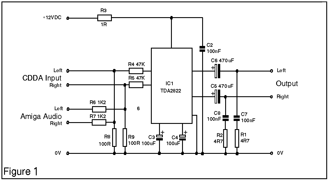
The 2 audio sources are fed into the inputs of the chip via the resistor array comprising of R4 to R9. The TDA2822 does it's work and the outputs are fed out through C5 and C6. These capacitors are present to block potentialy harmful DC current reaching the output conections. R3 is a small current limiting resistor and the decoupling is done via C2. Due to the fact that this project will be run from the computers power supply, decoupling of the electrical supply isn't really needed, but should you decide to run it from a different supply, a 470uF electrolytic capacitor should be fitted across the supply rails the same as C2. R1 and R2 give a preset output impedance of about 8 ohms and should suffice for most applications.
Firstly, we need to mark out and cut the stripboard. You will need a piece which is 19 holes long by 7 holes high. It is possible to cut the board by scribing along the strip of holes to cut with a craft knife and ruler. Once the board has been scribed gently flexing it in either direction will result in it cracking. Hopefully, if you made the scribes deep enough, it will crack along the marked lines. Do take care when trying to crack the board, do it very gently until you hear it start to crack. Otherwise it is a job for a hacksaw and lots a patience. Note that the strips should run along the board and not up and down. The picture below shows how it should look, and also shows where the traces should be cut. These cuts can be made very simply by using a drill bit of about 5 or 6mm in diameter. Rotate the drill by hand in the hole that corresponds to the cut in the trace. The drill will start to remove the copper. Keep going until all the copper around the hole is removed. Repeat this process for all the cuts, 14 in all. An important note to make here is to make sure that all the bits of copper are removed otherwise these will short out neighbouring traces. Using a craft knife, run it down the insulator strips at each trace to ensure they are clear. If you have a continuity tester or a multimeter, check that no short circuits exist. Care should be taken when handling stripboard as it can be very fragile, and too much pressure in one area can lead to the board cracking along a run of holes. If you need to push hard, (you may have a blunt drill bit!), support the board on a hard surface.
Required Tools
| Optional but useful
|
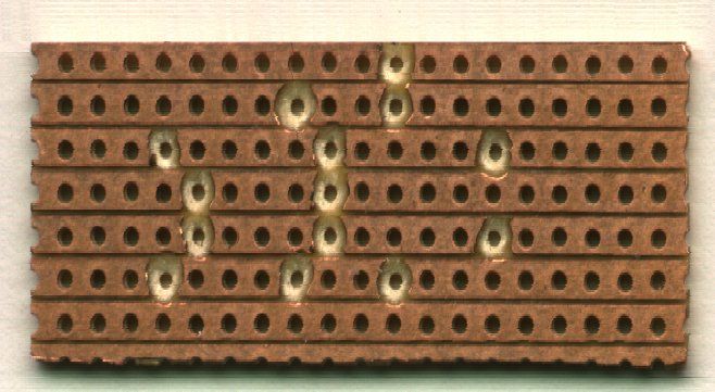 Figure 2
The wire links are fiddly so it is probably better of to start with these. Figure 3 shows how the links fit in. A tip here is to use the legs cut off the components to make the links, but do make sure you leave enough wire on the components to allow soldering.
Because of the physical size of the traces on stripboard it makes soldering quite difficult to the beginner. To ease this situation I would recommend you buy one of refillable gas soldering irons. There are quite a few different ones around, but the Portasol range of irons are very good. They are also supplied with a range of soldering tips, as you will need a very fine tip to avoid getting solder all over the place. Most mains soldering iron tips may be too large, but you could file them down.
Another benefit of a gas iron is the heat. Many components don't like excessive heat especially chips and the TDA2822 is no exception to this. The chip will withstand 300 degrees for about 10 seconds but any more will undoubtedly damage the part beyond useability. With a gas iron you can alter the tip heat by turning up the gas setting. This means that you can apply the heat faster and more locally hopefully avoiding damaging anything. If you are unsure about soldering small items or have never soldered before, it maybe advisable to have a little practice on some of the stripboard offcuts.
Soldering is the most important part of any kit building, as not enough heat will result in something known as a 'cold solder joint'. These set up a large resistance at the joint and can be a real pain to track down, but by the same token, too much heat will start to kill electronic components.
Start from the left hand side and work your way across. As each component goes in, the legs should appear through the board into a trace. If for some reason you end up with a leg on a cut, you have either put it in the wrong place, or you have the board the wrong way round. Capacitors would be next, and again start from the left and work across. Refering to figure 4 again, note that C3 to C6 are electrolytic and, as such, are polarised.
This means that they have to go in the right way around. If you put them in backwards they don't work well. Each of the capacitors has markings on the body, usually in the form of a line that points to one of the legs. It may have 'minus' signs in the line and this shows that the indicated leg is the cathode or negative connection. Figure 4 shows the polarity of these parts. C2, C7 and C8 are not polarised so they can be fitted either way around.
Then comes the CDDA header socket. Again care should be taken to avoid shorts with the wire link L1. And lastly the TDA2822 chip itself. One note here is that the chip has to be orientated correctly. If you look at the top of the chip you'll see that it either has a small scollop in one end or a small dot. In the case of the dot, this marks pin 1, whereas the scollop if it were at the top, pin 1 will be the one at the top left. A warning here is that if you do manage to put the chip in incorrectly you'll damage it, so figure 4 shows that pin 1 is at the bottom right. In effect the chip is in upside down.
This is not too bad on a zorro'd Amiga as there are always ways of geting cables in and out. If you are thinking of using this on an Amiga 1200 with an external CD Rom then you'll have to make up the leads to suit your type of setup. If all else fails you could opt to solder straight onto the back of the audio sockets from inside the machine. Although possible, it is extremely fiddly and involves heat on a lot of components very local to the sockets. Use it as a last resort.
So our master has phono leads to bring the audio back into the machine, and it has a 3.5mm stereo socket on a lead for the PC type speakers to be plugged into. This again depends on how you have your audio connected up. You could always wire up 2 phono sockets on the outputs to replace the originals.
These cables should be made from sheathed coaxial cable to give a good earth screen around the in/out cables. This helps to cut down on the electrical noise from inside the computer. Things like disk drives, hard drives etc can sometimes interfere, and a good screening with eliminate some of this. The power is taken from the 12V lines running out of the power supply. The easiest way to tap into these would be to find a vacant power connector. The connectors for hard disks has the power we need. 2 Lengths of cable, one red and one black, should be used for this and are connected up as in figure 5 below.
Here we show a hard disk connector
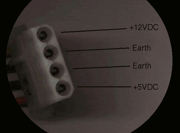 Figure 5
but a spare floppy drive connector would do just as well. In fact, if you have a multimeter, you can take a 12VDC supply from pretty much anywhere you can find one.
Repeat the process for the CDDA socket, checking first the left and right together. Is it greater than 150 ohms? Good. The last thing is to measure the value across the outputs. This should typically be high, at least 50K, but don't worry about being exactly as specified. Different component tolerances will affect these readings.
Simon Archer
|